Display (ST7789 240×240)
A square 240×240 ST7789 SPI module with an 8-pin header. Power first, then the five SPI wires.
Before you start
Checkpoint 3 passed. USB unplugged while you seat jumpers. The SHT40 power and I2C wires stay on.
Warning
Power from 3V3 only. The display's SDA must never share a wire with the SHT40's SDA.
Pin names
Match your module's printed labels. Clock may read SCL or SCK (same net). SDA here is SPI MOSI, not I2C.
| Pin | Meaning | ESP32 pin |
|---|---|---|
SCL / SCK |
SPI clock | GPIO12 |
SDA |
SPI MOSI. Not I2C | GPIO11 |
RST |
Reset (sometimes RES) |
GPIO7 |
DC |
Data or command | GPIO9 |
CS |
Chip select | GPIO10 |
BL |
Backlight control | GPIO21 |
1. Power
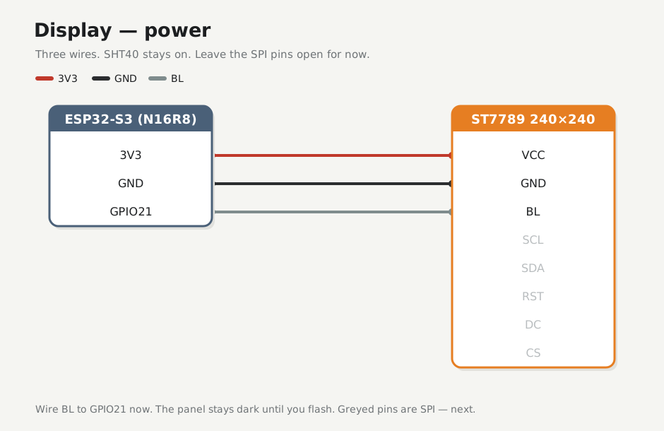
| From | To | |
|---|---|---|
+ rail (3V3) |
Display VCC | |
− rail (GND) |
Display GND | |
| GPIO21 | Display BL |
Leave the SPI pins open for now. Plug into COM and check that the module is cool, with about 3.3 V on VCC if you have a meter. Unplug before adding SPI.
BL → GPIO21
Firmware will PWM this pin later. Wire it now; do not expect the panel to light on this page.
2. SPI
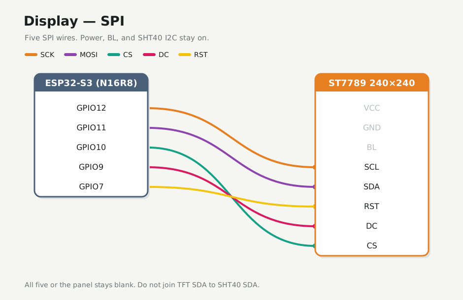
| ESP32 | Display | |
|---|---|---|
| GPIO12 | SCL (or SCK) | |
| GPIO11 | SDA (MOSI) | |
| GPIO10 | CS | |
| GPIO9 | DC | |
| GPIO7 | RST |
All five jumpers. Leave the panel dark until you flash.
If it fails
| Symptom | Fix |
|---|---|
| Module warm | Unplug. Check for 5V on VCC or a shorted pin |
| Meter doesn't read about 3.3 V on VCC | Confirm the ESP32 still feeds the + rail (checkpoint 2) |
Checkpoint 4
- Display VCC and GND are on the 3V3 and GND rails, and BL is on GPIO21
- The module is cool with COM plugged in
- All five SPI wires are in: GPIO12, 11, 10, 9, 7 to SCL, SDA, CS, DC, RST
- Display SDA is not joined to SHT40 SDA
Stop here until every box is ticked.
Next: Validate